<- previous index next ->
Recent update.
There are many file formats that may be of interest.
Collected here are a tiny fraction of what is available.
Search the web for code to read and convert formats.
Adapt existing code to the language of your choice.
AVS UCD data
AVS UCD data format
UCD cyl1.inp demonstrating boundary conditions
This file defines a rectangular duct with a cylinder inside.
The Dirichlet and Neumann boundary conditions are specified
as well as the geometry.
cyl1.inp boundary definition
plot_ucd.c for plotting 3D UCD boundary
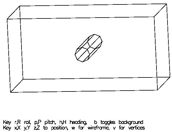
Extending UCD data to 4 dimensions
Without changing the basic UCD format,
the 4th coordinate can be provided along with
Dirichlet and Neumann boundary conditions.
pde_ucd4.inp 4D geometry
Source code to read UCD format
read_ucd.h C++ header
read_ucd.cc C++ code
test_read_ucd.cc C++ test
ucd1.inp test input data
ucd1.out test output results
ucd2.inp test input data
ucd2.out test output results
Ada Language implementation, including use in a PDE
pde_read_ucd.ads Ada package spec
pde_read_ucd.adb Ada package body
test_pde_read_ucd.adb test
test_pde_read_abc_ucd_ada.out test results
pde_process_ucd.ads Ada package spec
pde_process_ucd.adb Ada package body
test_pde_process_ucd.adb test
test_pde_process_abc_ucd_ada.out test results
make_abc_ucd.adb make abc_ucd.inp
abc_ucd.inp UCD file
abc_ucd.ads PDE definition spec
abc_ucd.adb PDE definition body
pde_abc_eq_ucd.adb PDE solver
pde_abc_eq_ucd_ada.out solution
UCD file with color, mechanical properties, ranges
The UCD File Format is very versatile.
This file is just a demonstration of the flexibility.
# ucd1.inp Sample AVS UCD File
#
9 8 1 3 5 9 nodes, 8 cells, 1 node data, 3 cell data, 5 model
1 0.000 0.000 1.000 Node coordinates
2 1.000 0.000 1.000
3 1.000 1.000 1.000
4 0.000 1.000 1.000
5 0.000 0.000 0.000
6 1.000 0.000 0.000
7 1.000 1.000 0.000
8 0.000 1.000 0.000
9 0.500 0.600 0.707
1 1 hex 1 2 3 4 5 6 7 8 cell id, material id, cell type, cell node numbers
2 1 tri 1 3 4
3 1 pt 1
4 1 tet 2 3 4 5
5 2 line 7 9
6 2 quad 2 4 6 8
7 2 prism 1 2 3 6 7 8
8 2 pyr 2 3 4 5 6
1 1 number of node components, size of each component
stress, lb/in**2 Component name, units name
1 4999.9999 Data value for each node component
2 18749.9999
3 37500.0000
4 56250.0000
5 74999.9999
6 93750.0001
7 107500.0003
8 5000.0001
9 5001.0000
1 3 number of cell components, size of each component
RGB, cell color component name, units name
2 1.0 0.0 0.0 Data value for each cell component
1 0.0 1.0 0.0 (Do not have to be in order, some may require order)
3 0.0 0.0 1.0
4 1.0 1.0 0.0
5 1.0 0.0 1.0
6 0.0 1.0 1.0
7 0.5 0.5 0.5
8 0.7 0.7 0.7
2 2 2 number of model components, size of each component
limits, min/max min/max component name, value description
range, min/max min/max component name, value description
1 -1.0 1.0 -1.0 1.0
2 -1.2 1.2 -1.3 1.3
3 -1.5 1.5 -1.6 1.6
4 -1.9 2.0 -2.0 1.9
5 -2.0 2.0 -2.0 2.0
<- previous index next ->
Other links
-
CMSC 455 home page
-
Syllabus - class dates and subjects, homework dates, reading assignments
-
Homework assignments - the details
-
Projects -
-
Partial Lecture Notes, one per WEB page
-
Partial Lecture Notes, one big page for printing
-
Downloadable samples, source and executables
-
Some brief notes on Matlab
-
Some brief notes on Python
-
Some brief notes on Fortran 95
-
Some brief notes on Ada 95
-
An Ada math library (gnatmath95)
-
Finite difference approximations for derivatives
-
MATLAB examples, some ODE, some PDE
-
parallel threads examples
-
Reference pages on Taylor series, identities,
coordinate systems, differential operators
-
selected news related to numerical computation
Go to top

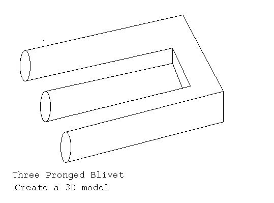
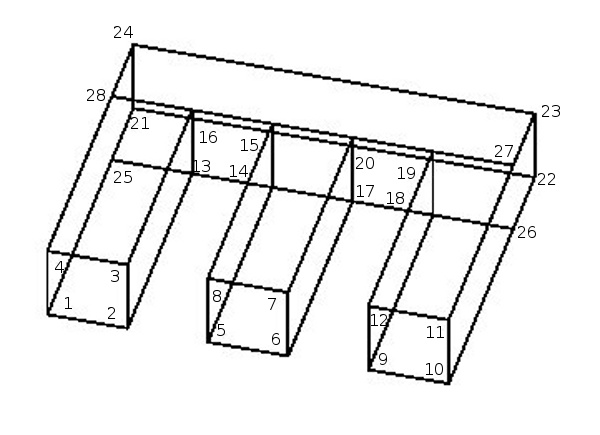 UCD format blivet.inp for above labeling