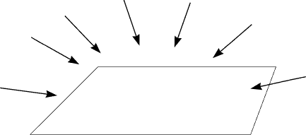
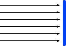
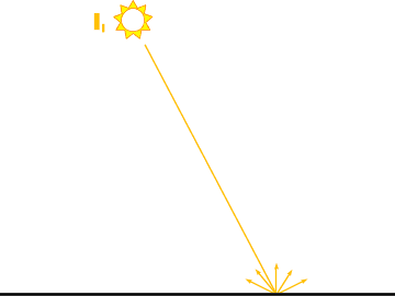
Ambient Light
Ia = intensity of ambient light |
Ambient Light
Ia = intensity of ambient light |
Ambient Light
Ia = intensity of ambient light |
Ambient Light
Ia = intensity of ambient light |
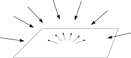
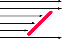
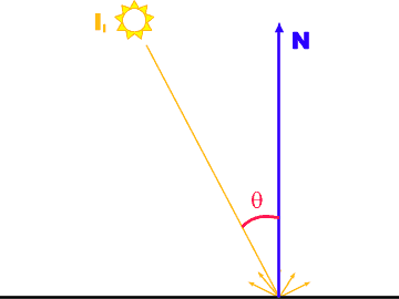
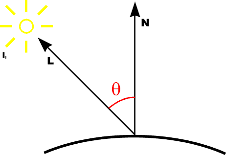
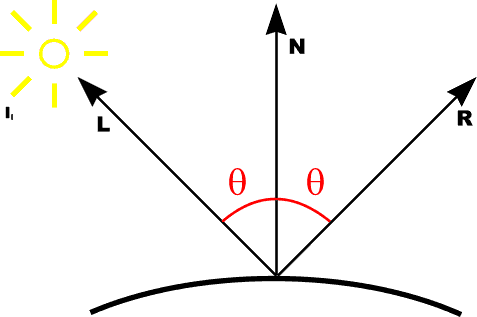
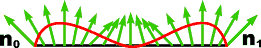
Lambert's LawIntensity of reflected light related to orientation
|
Lambert's LawIntensity of reflected light related to orientation
|
Lambert's LawIntensity of reflected light related to orientation
|
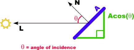
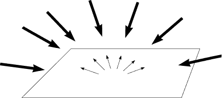
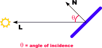
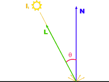
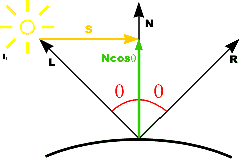
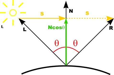
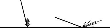
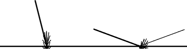
Diffuse Reflection
|
Diffuse Reflection
Idiff = kd Il cos [theta] |
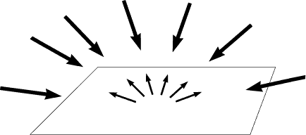
Diffuse Reflection
|
Diffuse Reflection
|
Diffuse Reflection
|
Diffuse Reflection
|
Combined Model
|
Combined Model with light source attenuation
where fatt = 1/dL2 - where dL is distance to light L |
Combined Model with light source attenuation
|
Combined Model with light source attenuation and atmospheric attenuation
It' = So It + (1 - So) Idct
|
Diffuse Shading Models
|


Flat Shading Algorithm
For each visible polygon
    evaluate illumination model with polygon normal

    For each scanline
	For each pixel on scanline
	    Fill with calculated intensity
|
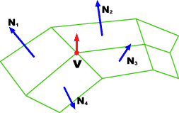
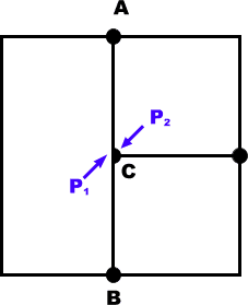
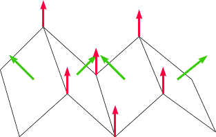
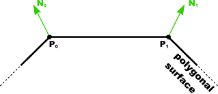
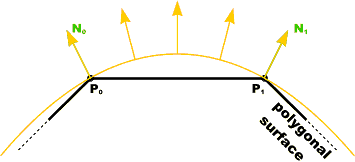
The normal vector at vertex V is calculated as the average of the surface normals for each polygon sharing that vertex
|
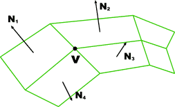
Surface NormalsThe normal vector at vertex V is calculated as the average of the surface normals for each polygon sharing that vertex
|
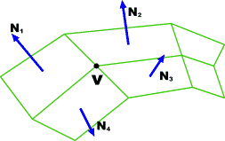
Vertex NormalsThe normal vector at vertex V is calculated as the average of the surface normals for each polygon sharing that vertex
|
Gouraud Algorithm
For each visible polygon
    evaluate illumination model at vertices
       using vertex normals

    For each scanline
        calculate intensity at edge intersections
	    (span extrema) by linear interpolation

	For each pixel on scanline
	    calculate intensity by interpolation of
	        intensity at span extrema

(like scan conversion with vertex colors)
|
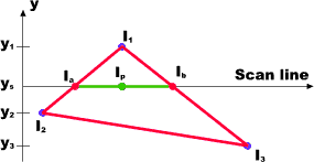
Gouraud Calculations
|
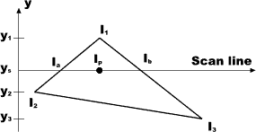
Gouraud Calculations
(1) calculate intensity at vertices (I1, I2, I3) from illumination model. |
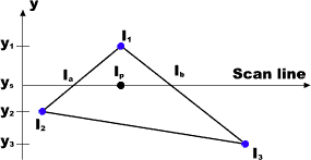
Gouraud Calculations
(1) calculate intensity at vertices (I1, I2, I3) from illumination model. (2) interpolate vertex intensities along edges (Ia, Ib) |
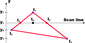
Gouraud Calculations
(1) calculate intensity at vertices (I1, I2, I3) from illumination model. (2) interpolate vertex intensities along edges (Ia, Ib) (3) interpolate intensities at span extrema to pixels (Ip) |
Problems with Interpolated Shading(1) Polygon silhouette - edge still polygonal (2) Perspective distortion - interpolation in screen space, rather than object space |
Problems with Interpolated Shading(1) Polygon silhouette - edge still polygonal (2) Perspective distortion - interpolation in screen space, rather than object space (3) Orientation dependence
|
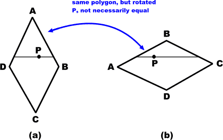
Problems with Interpolated Shading(1) Polygon silhouette - edge still polygonal (2) Perspective distortion - interpolation in screen space, rather than object space (3) Orientation dependence
(4) Problems at shared vertices
|
Problems with Interpolated Shading(1) Polygon silhouette - edge still polygonal (2) Perspective distortion - interpolation in screen space, rather than object space (3) Orientation dependence
(4) Problems at shared vertices
(5) Unrepresentative vertex normals
|
Combined ModelI = Iamb + Idiff + Ispec = ka Ia + kd Il (N.L) + ks Il (N.H)n |
Combined Model With Multiple LightsI = Iamb + sum[i]( Idiff + Ispec ) for N lights = ka Ia + sum[i]( kd Ili (N.L) + ks Ili (N.H)n ) |
Combined Model With Multiple LightsI[l] = Iamb[l] + sum[i]( Idiff[l] + Ispec[l] ) for N lights = ka[l] Ia[l] Od[l] + sum[i]( kd[l] Ili[l] (N.L) Od[l] + ks[l] Ili[l] (N.H)n )(* [l] - lambda) No specular color given => highlights light color (plastic) |
Combined Model With Multiple Lights and Metallic HighlightsI[l] = Iamb[l] + sum[i]( Idiff[l] + Ispec[l] ) for N lights = ka[l] Ia[l] Od[l] + sum[i]( kd[l] Ili[l] (N.L) Od[l] + ks[l] Ili[l] (N.H)n Od[l] )(* [l] - lambda) For metallic highlights, specular reflection must be wavelength dependent. |
Combined Model With Multiple Lights and Metallic Highlights
I[l] = Iamb[l] + sum[i]( Idiff[l] + Ispec[l] ) for N lights For even more accurate highlights, specular reflection coefficient depends on both wavelength and angle of incidence Ks([l], [t]). (* [l] - lambda, [t] - theta) |
Combined Model With Multiple Lights, Metallic Highlights and Distance Attenuation
I[l] = Iamb[l] + sum[i]( Idiff[l] + Ispec[l] ) for N lights Where di is distance to light i Possible f(di) = 1 / (a0 + a1 di + a2 di2) a1 di - linear falloff |
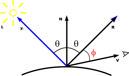
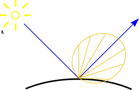
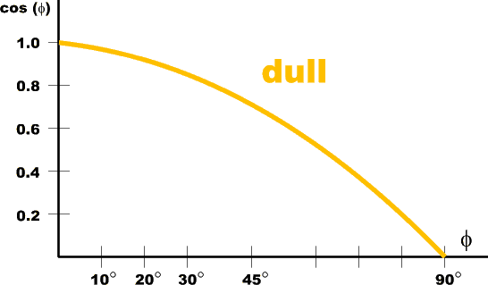
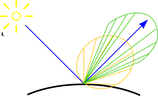
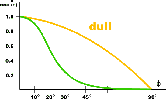
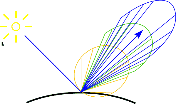
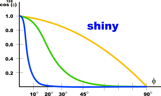
Specular Reflection
|
Specular Reflection
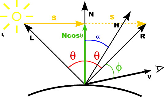
Ispec = ks Il cosn[phi] where: |
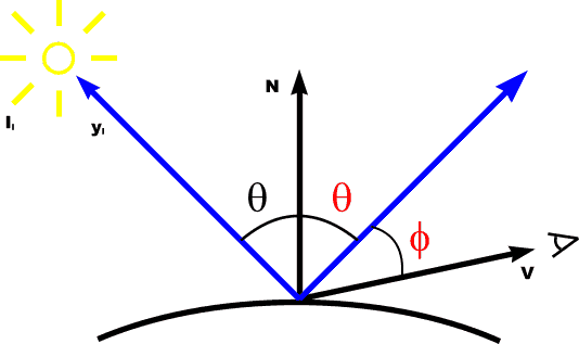
Specular Reflection
Ispec = ks Il cosn[phi] where: |
Specular Reflection
For specific wavelength: Ispec[l] = ks[l] Il cosn[phi] => Not dependent on surface color -> white highlights |
Specular Reflection
For specific wavelength: Ispec[l] = ks[l] Il Os[l] cosn[phi] => colored highlights |
Specular Reflection
|
Specular Reflection
|
Specular Reflection
|
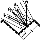
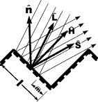
Calculating Reflection Vector
|
Calculating Reflection Vector
R is L mirrored about N |
Calculating Reflection Vector
R is L mirrored about N |
Calculating Reflection Vector
R is L mirrored about N |
Calculating Reflection Vector
R is L mirrored about N |
Calculating Reflection Vector
R is L mirrored about N Alternatively: use halfway vector H |
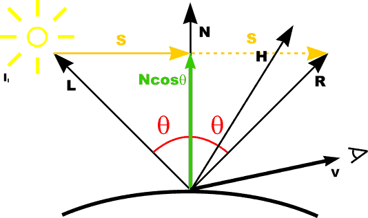
Calculating Reflection Vector
R is L mirrored about N Alternatively: use halfway vector H maximum highlight when H = N (because then R = V) |
Calculating Reflection Vector
R is L mirrored about N Alternatively: use halfway vector H maximum highlight when H = N (because then R = V) Two methods:
|
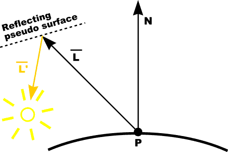
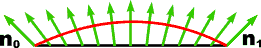
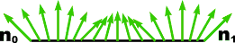
Advanced Point Lights: Warn ModelConcept: control light direction with hypothetical reflecting surface (only specular)
|
Advanced Point Lights: Warn ModelConcept: control light direction with hypothetical reflecting surface (only specular)
Light intensity affected by pseudosurface orientation |

Advanced Point Lights: Warn ModelConcept: control light direction with hypothetical reflecting surface (only specular)
Light intensity affected by pseudosurface orientation |
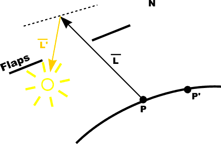
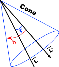
Advanced Point Lights: Warn ModelFlaps and cones mimic photographic light characteristics
|
Phong Shading
|
Phong Shading
(approximation to curved surface) |
Phong Shading
where Pa, Pb, Pc are pixels covered by this polygon (approximation to curved surface) Approximate with normals interpolated between vertex normals: |
Phong Algorithm
For each visible polygon
  For each scanline
    Calculate normals at edge intersections (span
           extrema) by linear interpolation

    For each pixel on scanline
      Calculate normal by interpolation of normals
	   at span extrema

      Evaluate illumination model with that normal
|
Filtered Transparency
|
Filtered Transparency
I[f] = I[f]1 + kt1 Ot[f] I[f]2 Must composite back to front (or front to back) |
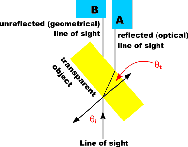
Refractive Transparency
|
Refractive Transparency
|
Calculating Refraction Vector
|
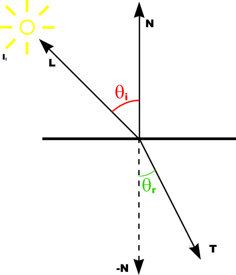
Calculating Refraction Vector
|
Calculating Refraction Vector
|
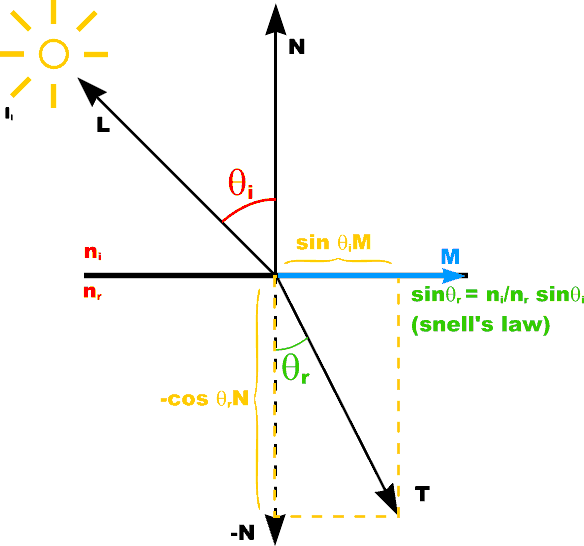
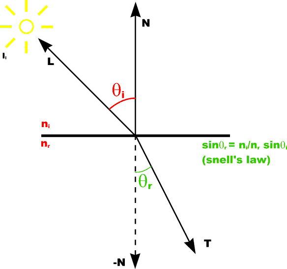
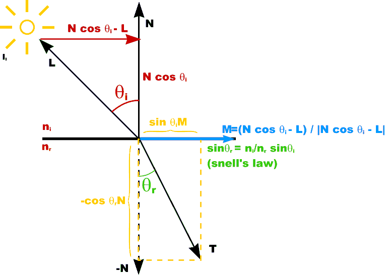
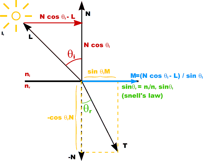
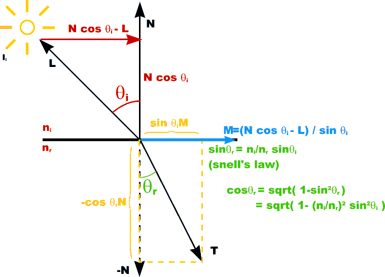
Calculating Refraction Vector
T = sin [theta]rM - cos[theta]rN |
Calculating Refraction Vector
T = sin [theta]rM - cos[theta]rN |
Calculating Refraction Vector
T = sin [theta]rM - cos[theta]rN |
Calculating Refraction Vector
T = sin [theta]rM - cos[theta]rN |
Calculating Refraction Vector
T = sin [theta]rM - cos[theta]rN |
Calculating Refraction Vector
T = sin [theta]rM - cos[theta]rN |
Calculating Refraction Vector
T = sin [theta]rM - cos[theta]rN |
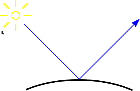
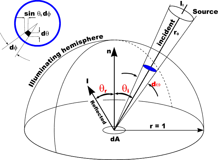
Light Source Energy
|
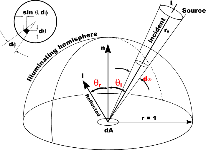
Light Source Energy
Illumination from a light source depends on the solid angle [omega] subtended by that light source [omega] = [integral]2[pi] ( [integral]tan-1(r's / r0) ( sin [theta] d[theta] d[phi] ) ) = 2[pi] (1 - cos (tan-1 rs/r0)) |
Light Source Energy
Illumination from a light source depends on the solid angle [omega] subterded by that light source [omega] = [integral]2[pi] ( [integral]tan-1(r's / r0) ( sin [theta] d[theta] d[phi] ) ) = 2[pi] (1 - cos (tan-1 rs/r0))sometimes approximated by = [pi] rs/r0 when rs/r0 << 1 |
Light Source Energy
Illumination from a light source depends on the solid angle [omega] subterded by that light source [omega] = [integral]2[pi] ( [integral]tan-1(r's / r0) ( sin [theta] d[theta] d[phi] ) ) = 2[pi] (1 - cos (tan-1 rs/r0))sometimes approximated by = [pi] rs/r0 when rs/r0 << 1 Incident energy: |
Surface physics
Smooth dielectric (like glass) |
Surface physics
Rough dielectric (like glass) |
Surface physics
Smooth conductor (like metal) |
Surface physics
Rough conductor (like metal) |
Surface physics
Composite (like plastic) |
Bidirectional Reflectance
|
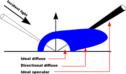
Bidirectional Reflectance
Reflected light is related to incident light = bidirectional reflectance |
Bidirectional Reflectance
Reflected light is related to incident light = bidirectionalreflectance Cook - Torrance Illumination Model: |
Geometric Attenuation
For rought surfaces |
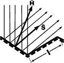
Geometric Attenuation
Torrance - Sparrow model: |
Bump Mapping
|

Bump MappingStraight Phong Shading
|
Bump MappingStraight Phong Shading Phong with bump mapping |
Bump MappingStraight Phong Shading Phong with bump mapping |
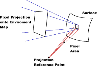
Environmental Mapping
Projecting a pixel area to a surface, then reflecting the area to the environment map. |
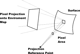
Environmental Mapping
Projecting a pixel area to a surface, then reflecting the area to the environment map. |
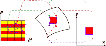
Texture Mapping
|
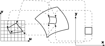
Texture Mapping
For each pixel |
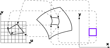
Texture Mapping
For each pixel
  determine position on object surface for
     each pixel corner (use inverse viewing
     transformation)
|
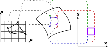
Texture Mapping
For each pixel
  determine position on object surface for
     each pixel corner (use inverse viewing
     transformation)

  determine position in texture map for
     each pixel corner
|
Texture Mapping
For each pixel
  determine position on object surface for
     each pixel corner (use inverse viewing
     transformation)

  determine position in texture map for
     each pixel corner

  get color (or average color) from
     texture map
|
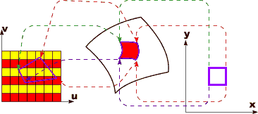
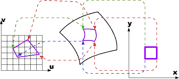
Texture Mapping
For each pixel
  determine position on object surface for
     each pixel corner (use inverse viewing
     transformation)

  determine position in texture map for
     each pixel corner

  get color (or average color) from
     texture map

  map color back onto screen pixel
|
![[prev]](common/prev.gif)
![[next]](common/next.gif)
| Made by dynaPage 0.2 |